|
MECHANICAL AND METALLURGICAL EVALUATION Report No. 011206 1 December 2006
Table of Contents 1 INTORDUCTION..........................................................1 INTRODUCTION Detailed mechanical and metallurgical tests were carried out to determine the behaviour of the NOVOTEXI 440 roofing sheet profile and the inherent metallurgical properties of the steel sheet used in its production. The mechanical behaviour of the profile was determined through loading tests on a “roof element” using three different purlin spans. Point loading tests were also carried out. The metallurgical characteristics of the material of construction were determined through mechanical tests on laboratory specimens, metallographic evaluations and scanning electron microscopy. 1. INVESTIGATION PROCEDURES AND RESULTS 1.1 The NOVOTEXI 440 Roofing Profile
The NOVOTEXI 440 profile is shown in Figure 1. This profile has a unique interlocking and clipping mechanism that does not allow the sheet to unclip between purlin centres as a result of traffic on the roof or other types of loads. The product may be rolled from high tensile steel (ISQ 550) or from softer materials (ISQ 230-300). It may also be rolled in copper or aluminium sheets. Chromadek sheet is used in thin gauge (0.5mm) due to the high tensile strength of the material making the roof lighter, reducing costs and facilitating installation. The profile uses concealed cleats for fastening which offer a number of advantages. They reduce or eliminate the probability of corrosion between the roofing sheet and the fastener, they eliminate the need for drilling the sheets, eliminate leaks through holes in the sheets, allow movement of sheet due to temperature changes thus avoiding buckling and possible fatigue problems and give the roof an aesthetically pleasing appearance. The cleats are formed from 1mm thick galvanised sheet which gives them more than adequate strength and rigidity. Installation of the profile is relatively easy reducing the level of workmanship required which results in reduced cost. It may be roll formed and installed in long lengths on roofs with a pitch as low as 2º. The profile and the forming process are such that no spur marks are evident after interlocking the sheets, making NOVOTEXI 440 suitable for side cladding as well as for roofing. The integrity of the Chromadek coating is not compromised by the roll forming process and the corrosion properties of the roof are therefore not prejudiced. 1.2 Loading TestsThe test bed was rectangular and was made from welded steel channel of 100X50X6mm. The length of the bed was 9m and its width 2.2m. The bed was supported by eight legs, one at each corner and two sets of legs, each 3m from either end. Lip channels of 100X50X20X2mm were used as purlins across the bed width. These were appropriately spaced on the bed to form the different spans required for the tests. Four sheets abreast were used to form the “roof element” for the tests. This formed a realistic roof element for testing which behaved like an actual roof might be expected to behave under similar conditions. The SABS Specification 0237:1991 was used as a guideline, the actual test conditions being more severe than those specified, whenever such conditions deviated from those of the Specification. 1.2.1 Negative Loading Test on 1.8m SpanFor this test the arrangement of the sheets was as shown in Figure 2. Loading was carried out through the use of sand bags all of which had been weighed and marked in advance. The first row of bags for the negative load test on the 1.8m span is shown in Figure 3. The bags were about 300mm centre to centre and the load was thus concentrated over a width of about 300mm with its middle coincident with that of the middle span. The SABS specification 0273:1991 describes tests with uniformly distributed load. This would not be practical in this case due to the very high strength and rigidity of the roof. With distributed load one would be testing the strength of the roof structure rather than that of the roofing profile. The second row of sand bags is shown in Figure 4 while the third and fourth rows are shown in Figure 5. In this way the roof element was loaded until permanent damage to the sheeting became apparent. The sagging of the roof element was measured during both the loading and unloading cycles of the roof element. This was achieved by hanging a magnetic measuring tape from the bottom of the roof element in the middle of the loaded area. Measurements of distortion were taken at the start of the loading test and with every row of sand bags loaded onto the roof element. The measurements were taken against a fixed point as indicated in Figure 6. The results of this test were as follows.
Plots of deflection against load are shown in Figure 7 for loading and unloading. It is evident that on both loading and unloading the behaviour of the roof element was substantially elastic showing deflection proportional to the load. A permanent set of 12mm remained in the roof element which was largely the result of the straightening of the cleats. The appearance of the roof element after unloading is shown in Figure 12. It is evident that the roof element substantially recovered after upon unloading. The purlins adjacent to the load showed permanent bowing of about 2mm at the mid point. 1.2.2 Positive Loading Test on 1.8m SpanA positive loading test on a 1.8m span was carried out on a new roof element ie new roofing sheets. Polyclosures were used to fill in the troughs of the profile and so avoid excessive load concentration on the ridges of the sheets. The arrangement of the polyclosures was as shown in Figure 13. Loading was carried out as described previously eventually attaining a load of 1086kg. The roof element with this load in place is shown in Figures 14 and 15. It is evident that the roof element deflected under this extreme load but it still held together very well there being no decoupling of the sheets. There was some evidence of “rippling” in the troughs of the sheets close to the loading point (Figure 16) which disappeared upon unloading. The end of the roof element lifted slightly off the end purlin as indicated in Figure 17 and the purlins adjacent to the loading zone showed some bowing (Figure 18) with the load still in place. Upon unloading the roof element was checked for permanent set in the longitudinal and transverse directions by use of a steel straightedge (Figure 19). In the longitudinal direction the highest amount of permanent set was about 2 to 3mm over a distance of about 2m of the profile ridge. In the transverse direction the permanent set was greater in the two middle sheets the distance between the straightedge and the ridges being about 2 to 3mm at most. The purlins adjacent to the loading zone showed approximately 2mm of permanent set in the vertical plane and zero set in the horizontal plane. The readings of load and deflection for this test were as follows.
Plots of load against deflection are shown in Figure 20. It is evident that the behaviour of the roof element was fundamentally elastic there being a permanent set of 5mm upon unloading. 1.2.3 Point Loading on 1.8 and 2.2m SpansPoint loading tests were carried out as described in SABS specification 0237:1991. These involved the placing of a weight of 0.9kN on a wooden block 100X100X50mm resting on different parts of a two-sheet assembly. The weight was allowed to stand for 5 minutes before being removed. The sagging of the sheets was measured as described earlier for the roof elements and a visual examination was carried out for evidence of permanent damage. Point loading tests were carried out on spans of 1.8 and 2.2m in the trough, on the ridge and on the overlap of the assemblies. The point load test in the first trough of the 1.8m span assembly is shown in Figure 21 and a similar test on the first ridge in Figure 22. The results of these tests were as follows.
It is evident that the deflection of the roof element was almost totally elastic under the point loads showing permanent set of 3mm, in the worst case, upon unloading. There was no evidence of denting or any other form of mechanical damage to the sheeting. 1.2.4 Positive Loading Test on 2.2m SpanThe positive loading test on the 2.2m span was carried out in a fashion similar to that described for the 1.8m span roof element. The readings of deflection with increasing or decreasing load were as follows.
These results are plotted in Figure 23 and show that the roof element behaved elastically to a load of about 800kg. At 972kg it appeared that the roof element started to yield plastically. There was no unclipping of the sheets at any stage. On removal of the load small dents were evident in the middle sheets (Figure 24). 1.3 Metallographic ExaminationSections were taken from the severely deformed male and female overlap areas of a profiled sheet and examined microscopically to determine the condition of the material after forming. Similar sections were also taken through cleats to determine the metallurgical nature of the material. A section through undiformed sheet is shown in Figure 25. The galvanized coating is evident on both sides of the sheet while the paint coating is only evident on the top side (right of photograph) only. This is due to the reduced thickness of the paint coating on the underside of the sheet. The bend round the tight corner in the male part of the overlap is shown in Figure 26. The inner and outer coatings are shown in greater detail in Figures 27 and 28 respectively. It is evident that the coating integrity was unaffected. The microstructure of the roofing sheet (Figure 29) consisted of ferrite with a small amount of carbide typical of very low carbon steel. Cold rolling was evident by the elongation of the ferrite grains. The cleat material showed a microstructure of practically pure ferrite (Figure 30) indicative of a material with very low carbon content. 1.4 Electron MicroscopySections of the male and female overlap areas were examined in an electron microscope to determine the effects of the forming process on the integrity of the Chromadek coating. The apex of the male part of the overlap showed stretch marks but there was no evidence of disruption of the coating (Figures 31 and 32). The female part of the overlap showed no evidence of any effects due to the forming process (Figures 33 and 34). It should be borne in mind that the male part of the overlap is completely covered by the female part and is therefore not exposed to the weather. Thus, the properties of the female part of the overlap have the deciding effect on behaviour in the field. It should also be borne in mind that the bending severity in the female part of the overlap is substantially lower than that in the male part of the overlap. The forming process, therefore, is not expected to have an effect on the integrity of the coating. Tensile Tests on Sheet Material. The specimens were of 100mm gauge length and 20mm wide and yielded the following results.
L= longitudinal direction It is evident that all the specimens met the strength requirement of the ISQ specification very comfortably. The elongation of the longitudinal specimens was relatively low due to the extensive cold rolling of the material which contributes substantially to its strength but reduces its ductility. In these specimens there was a measurable difference between the yield stress and the ultimate tensile strength of the material. The transverse specimens showed a reduced amount of ductility, as might have been expected, and no measurable difference between the yield and ultimate strengths. The low transverse ductility did not have any detrimental effects on the roll forming process evidenced by the lack of any defects in the roll formed sheets. 1.5 Hardness TestsHardness tests were carried out on the roofing sheet and the cleat material and the following results were obtained. Cleat 143HV0.5 Roofing sheet 215HV0.5 These results are in keeping with the chemistry and the condition of the materials. 2. DISCUSSION The results of this evaluation are self explanatory and do not afford a lot of analysis other than to highlight some of the attributes of the roofing profile. The loading tests performed were of an extremely severe nature and the conditions used are not expected to be encountered in the field. Nevertheless the roof elements performed admirably despite the extreme loads they were placed under. Under the extreme loads used the profile eventually showed limited buckling but even then the roof element was still considered to be functional. It may be said that as far as positive loads on 1.8m and 2.2m spans are concerned the profile is practically indestructible. With negative loading the roof element was less rigid, as expected, but proved to be more than adequate in its load bearing capacity. If it is assumed that the load covered an area of 0.3X1.8m the pressure over this area on full load was about 7.6kN/m². This sort of pressure is not expected to be met in the field. And again it should be emphasised that the roof element remained functional after unloading there being no unclipping between sheets or between sheets and cleats. The roof elements tested exhibited elastic behaviour to very high loads which means that in the vast majority of cases the roof will recover fully once the forces acting on it are removed. The residual sagging measured in this evaluation was the combined effect of the extreme loads on the test sheets and the purlins. Nonetheless when the scale of the tests is considered it will be appreciated that the residual set was minimal particularly in the case of the positive loading runs. With negative loading both the deflection and the residual set were higher because all of the load was carried by the cleats which deformed plastically under load. It is, however, remarkable that the roof element was still in a functional condition after the experiment. The point loading tests proved that operators may stand or walk over the profile during the laying operation without damaging it. This is very important as it eliminates the need for walkways and speeds up the laying process. It also makes the process easier for the operators on the job. Chromadek sheeting has been in use for a number of years and has proved itself in many different conditions. It provides excellent corrosion resistance due to its duplex coating system. Cracking of the coating is avoided due to the limited thickness of the zinc layer and the plasticity/elasticity of the paint coating. Cracking in the NOVOTEXI 440 profile is not likely due to the generous radii used in the overlap. The properties of the steel sheet have been shown to be adequate in terms of the ISQ specification. The strength of the material at 550 to 620 MPa is significantly higher than that of the average structural steel. CONCLUSIONSThe NOVOTEXI 440 roofing profile proved to be practically indestructible under positive and negative loading conditions of an extreme nature. The roof elements tested behaved elastically to very high loads and remained practically functional even after permanent damage became evident. The sheet steel used for the profile is of high strength giving the profile very high rigidity and resistance to plastic deformation. The Chromadek coating and the design of the profile guarantee resistance to corrosion. A Koursaris
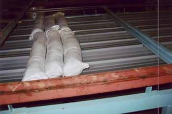 FIGURE 3 FIGURE 3
|
||||||||||||||||||||||||||||||||||||||||||||||||||||||||||||||||||||||||||||||||||||||||||||||||||||||||||||||||||||||||||||||||||||||||||||||||||||||||||||||||||||||||||||||
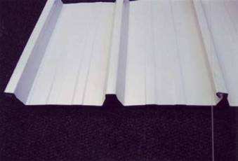 FIGURE 1
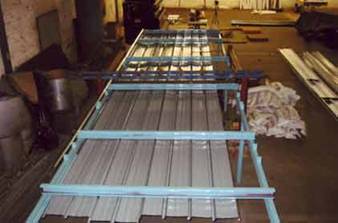 FIGURE 2
 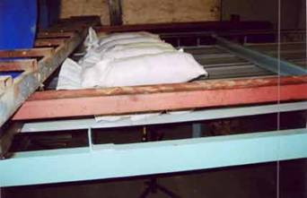 FIGURE 4
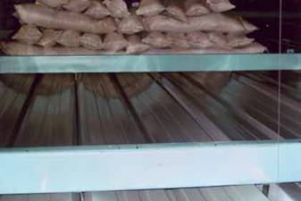 FIGURE 5
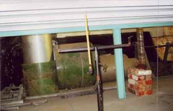 FIGURE 6
 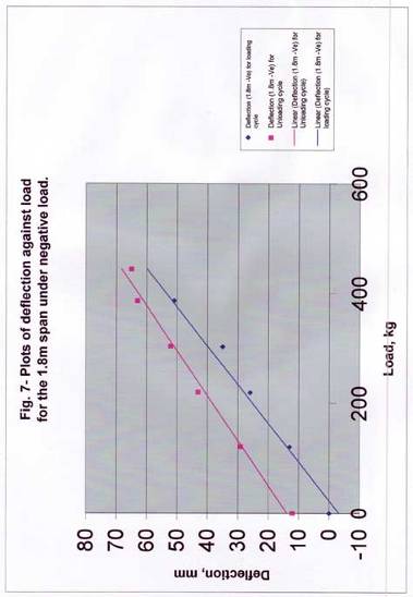 FIGURE 7
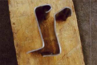 FIGURE 8
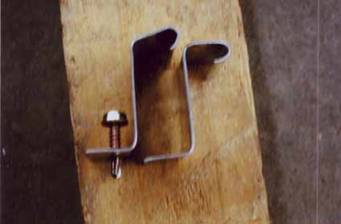 FIGURE 9
 FIGURE 10
 FIGURE 11
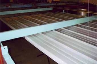 FIGURE 12
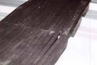 FIGURE 13
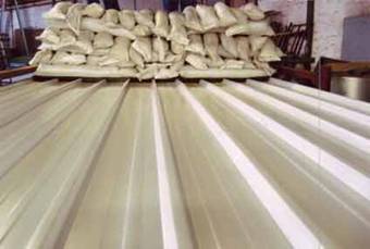 FIGURE 14
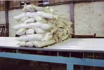 FIGURE 15
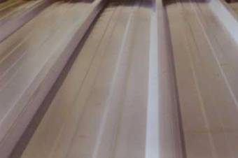 FIGURE 16
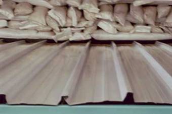 FIGURE 17
 FIGURE 18
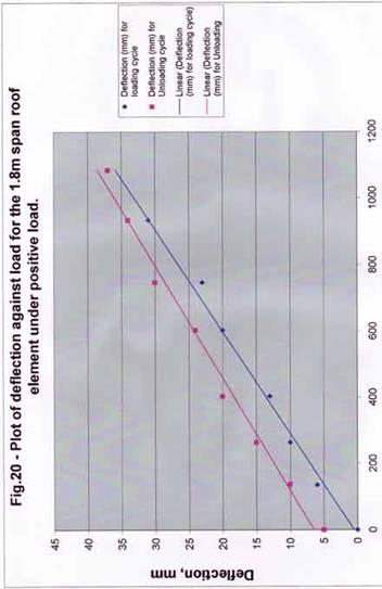 FIGURE 20
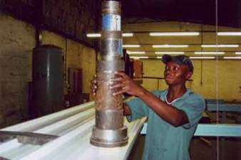 FIGURE 21
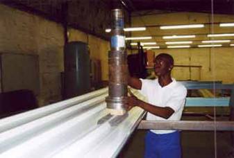 FIGURE 22
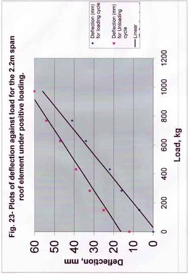 FIGURE 23, 200X
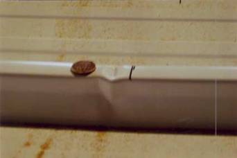 FIGURE 24, 100X
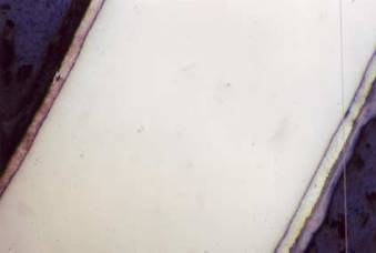 FIGURE 25, 200X
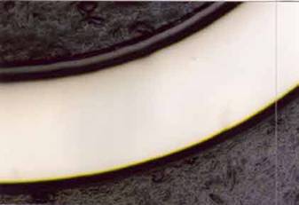
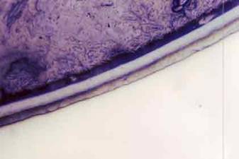 FIGURE 27, 200X
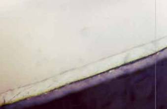 FIGURE 28, 500X
 FIGURE 29, 200X
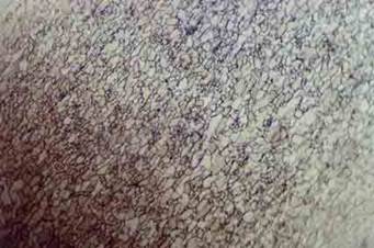 FIGURE 30, 100X
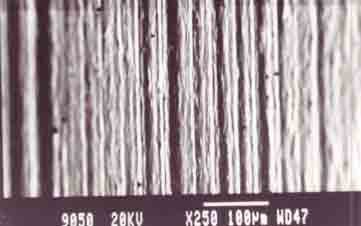 FIGURE 31
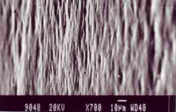 FIGURE 32
 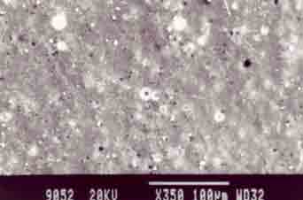 FIGURE 33
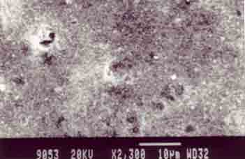 FIGURE 34