|
|

|
Allowable Load Tables
|
Factored Load Tables
|
|
|
 |
Material:
ASTM446 grade C (galvanised to Z275) |
|
|
GENERAL
- Bond-Dek floor slabs are basically one-way slabs
designed to carry uniformly distributed loads. The
design does not cater for heavy concentrated loads
or moving loads. Where these occur the design should
be referred to a civil/structural engineer.
- Calculations are generally in accordance with
BS5950 : Part 4 1984 (limit states design). Deflection during
construction calculated at span/180.
- Where the Bond-Dek is not fixed directly to the
end supports (e.g. shear studs, hilti nails, etc.)
steel closer pieces or transverse straps are
required along the ends.
- For normal applications of Bond-Dek steel
floors, no additional reinforcing other than a light
mesh for shrinkage control is required, typically
193 mesh.
- For "Fire Applications" of Bond-Dek
floors, welded steel mesh reinforcement of 8 mm
diameter steel bars at 200 mm spacing in each
direction is required, with minimum top cover along
supports (typically on top of shear studs). This
gives the following ratings for a nominal
superimposed load of 2,5 kN/m2 maximum,
for spans up to 3,0 m:
120 minutes - where the thickness of the slab plus
any concrete screed is greater than 170 mm, and
90 minutes - where the thickness of the slab plus
any concrete screed is less than 170 mm.
For further information on fire applications contact
Brownbuilt. N.B. All tabulated values serve as a guide
only for single span conditions, and should be certified
and approved by a civil/structural engineer.
ACCESSORIES
The following accessories are available for use with
Bond-Dek:
Steel side and end closers, seif-tapping screws, pop
rivets, hammer drive screws and flashings made to order. |
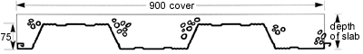
Section Properties of Steel Decking - Simply Supported
Condition
|
Nominal thickness (mm) |
Effective thickness (mm) |
Area of steel per metre width or
cross section (mm²) |
Mass per square metre (kg/m²) |
Minimum reduced "Z" per
metre width (10³mm³) |
Reduced "I" per metre
width (1065mm4) |
Effective depth of Bond-Dek (mm) |
Neutral axis from bottom of Bond-Dek
(mm) |
|
0,8 |
0,76 |
993 |
7,8 |
22,2 |
0,884 |
74,76 |
35,05 |
|
1,0 |
0,96 |
1254 |
9,85 |
30,3 |
1,170 |
74,96 |
36,38 |
|
1,2 |
1,16 |
1515 |
11,9 |
38,7 |
1,463 |
75,16 |
37,37 |
|
|
|
|
(Read entire procedure before pouring concrete) |
| Bond-Dek panels
act as formwork for wet concrete and
reinforcing for the slab. To commence
installation the first Bond-Dek panel is
placed in the required position with the
male interlocking rib pointing in the
direction of the laying as per sketch
(right). Place the female interlocking rib
to the outside. Place the interlocking
female rib of the second panel onto the male
rib of the first panel at an approximate
45° angle and then lower panel down onto
supports locking the side lap together (see
sketch, right). repeat for each additional
panel. |
 |
|
|
 |
End Lapping of Sheets
The standard procedure is to lap Bond-Dek and
not butt joint it.
To end lap Bond-Dek panels cut back 25 mm on male
and female interlocking ribs on the bottom panel
then overlap top panel.
Fix with Top Speed screws into beam to ensure
lateral stability at supports. |
|
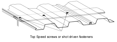
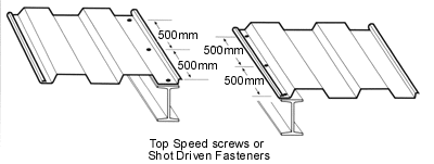
Structural Steelwork
Bond-Dek panels can be conveniently fixed to steel
supports with either "Top Speed" screws or
shot driven fasteners. One fixing in each pan is
required. |
 |
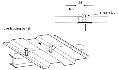 |
Shear Studs
If shear studs are to be used these should be
placed in the pan of the panel over a beam. Where
panels are end lapped, this lap of 25 mm must be
to one side of the beam, allowing for shear stud
to be positioned through centre of the beam and
fixed through the bottom panel (see sketch, left) |
|
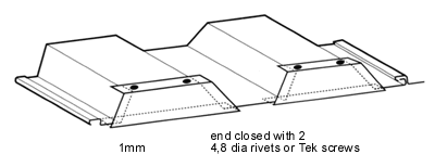
| When utilising a
closer at the ends of the Bond-Dek panels (see
sketch , right), this provides lateral stability
without the use of strapping. (Closer to fit
snugly over Bond-Dek.) |
 |
|
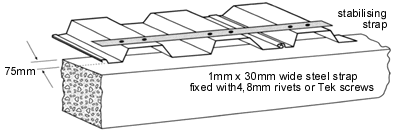 |
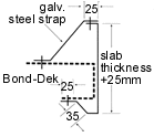
Concrete or Brick Construction
Before laying any Bond-Dek panels ensure that the top
face of the concrete beam or brick wall is level. An
uneven top face will result in an excessive amount of
concrete in places and therefore possible overloading.
Installation of the Bond-Dek is to simply place the
panels onto the concrete beams or the top of the
brick walls. A steel strap is placed across the panels
and fixed at each flute (see sketch, left). This is done
to ensure lateral stability while casting the slab. When
the deck is spanning its maximum, a steel strap should
be fixed at mid-span as well as at the ends. |
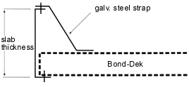
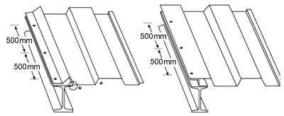
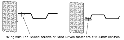
Side Fixing to Supporting Structure
Bend down cut edge of panel and fix with Top
Speed or shot driven fastener. Ensure angle * of
rib remains the same.
Alternatively a make-up Z-piece 75 mm deep can be
fixed to the beam and Bond-Dek. |
 |
|
|
Fixing to Concrete
|
 |
|
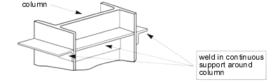
Fixing Around Columns
|
 |
|
 |
Kerb Flashing
Standard Kerb flashing is secured by riveting
the bottom of the deck to the bottom leg of
the Kerb flash, and the top of the Bond-Dek
rib. Kerb flashings to be a minimum of 1 mm
thick. |
|
|
|
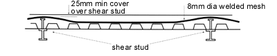
| For
"Fire Applications" of Bond-Dek floors,
welded steel mesh reinforcement of 8 mm diameter
steel bars at 200 mm centres in each direction is
required with minimum top cover along supports
(typically on top of shear studs). |
 |
|
Pouring Concrete
Pour concrete over load bearing beams. Never
exceed a concrete height of 300 mm and avoid load
concentrations, i.e. excessive equipment or
manpower. |
 |
|
Safe Load Tables
|
|
0,8 Thick Bond-dek
decking spans during construction (unpropped)
Allowing for a construction load of 1,5 kN/m²
plus wet concrete |
|
Slab depth (mm) |
140 |
150 |
160 |
170 |
180 |
190 |
200 |
210 |
220 |
230 |
240 |
250 |
|
Unpropped span (m) |
2,7 |
2,6 |
2,6 |
2,5 |
2,4 |
2,4 |
2,3 |
2,3 |
2,2 |
2,2 |
2,1 |
2,1 |
|
|
|
1,0 Thick Bond-dek
decking spans during construction (unpropped)
Allowing for a construction load of 1,5 kN/m²
plus wet concrete |
|
Slab depth (mm) |
140 |
150 |
160 |
170 |
180 |
190 |
200 |
210 |
220 |
230 |
240 |
250 |
|
Unpropped span (m) |
3,2 |
3,1 |
3,0 |
2,9 |
2,8 |
2,8 |
2,7 |
2,7 |
2,6 |
2,6 |
2,5 |
2,5 |
|
|
|
1,2 Thick Bond-dek
decking spans during construction (unpropped)
Allowing for a construction load of 1,5 kN/m²
plus wet concrete |
|
Slab depth (mm) |
140 |
150 |
160 |
170 |
180 |
190 |
200 |
210 |
220 |
230 |
240 |
250 |
|
Unpropped span (m) |
3,5 |
3,4 |
3,4 |
3,3 |
3,2 |
3,1 |
3,1 |
3,0 |
2,9 |
2,9 |
2,8 |
2,8 |
|
|
 |
! NEVER POUR CONCRETE AT MID-SPAN.
|
|
|
|
|
|
|